The temperature/humidity sensor I am using is a DHT11. <http://www.amazon.com/gp/product/B00BXWUWRA/ref=oh_aui_detailpage_o01_s00?ie=UTF8&psc=1>
The basic directions I followed were on the Adafruit website:
- Wiring: <https://learn.adafruit.com/dht-humidity-sensing-on-raspberry-pi-with-gdocs-logging/wiring>
- Software: <https://learn.adafruit.com/dht-humidity-sensing-on-raspberry-pi-with-gdocs-logging/software-install-updated>
Here are the python commands I used to get it to work (python has to be run using sudo, since we need su access to use the GPIOs).
*********************************
>>> import Adafruit_DHT
>>> sensor = Adafruit_DHT.DHT11
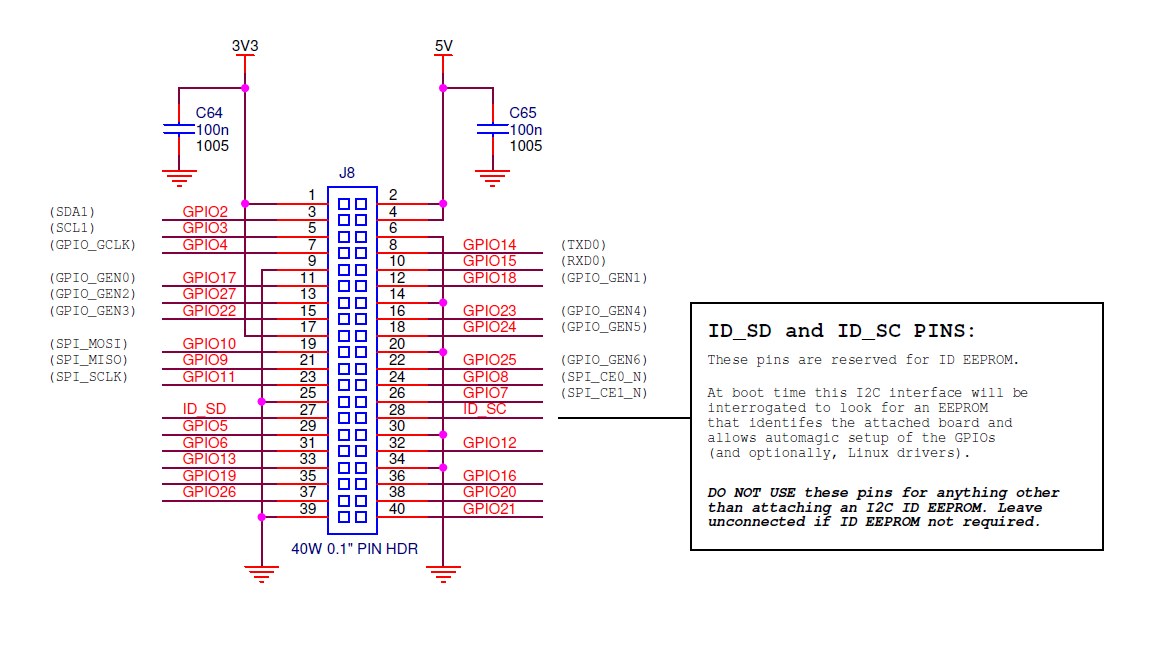
>>> pin = 4
>>> humidity, temperature = Adafruit_DHT.read_retry(sensor, pin)
>>> humidity
46.0
>>> temperature
24.0
>>>
*********************************
I currently have it set up using the breadboard. However, I got a reading earlier using connections directly with the GPIO in the Pi. That's not working now, however. It's something I'll have to look at later.
It looks like I can run this program anywhere as long as the file "Adafruit_DHT.py" is in the same directory (obviously, since the file needs to be imported).
I have seen some reviews showing preferences to the DHT22, so if I ever need to get a second temperature sensor, I can consider that one.
Update: December 24, 2014
ReplyDeleteI tried again with the temperature sensor attached directly to the GPIO pins. It worked. The problem was remembering the orientation of the pins. With the figure I included in this post, the orientation is correct when the Pi is turned so the pins are closest to the upper-right corner (ethernet and USB ports at the bottom).
Nice work! I can suggest a couple of reasons why you might want to add a resistor to your I2C data line:
ReplyDeleteThe default state of serial lines in I2C needs to be logic high. One common configuration of circuits that connect with I2C is to pull the line to ground when necessary, and "let go" when not. Having a resistor connected to Vcc lets the line "pull up" to the high value. Chips will often do this by setting a GPIO to 0 and then toggling its configuration between an output, pulling the line down, and an input, letting the line get pulled up by the resistor. You usually only see a device actively pushing the line to logic high when the IO pin isn't a tri-state setup. Your setup works without the resistor because the Raspberry Pi already has a pull-up resistor configured in it. But what if that fails? You'd lose the entire data connection due to a single resistor. Or perhaps your Raspberry Pi reboots; the line could go low, and cause devices to go into unknown states because they're anticipating data when none was intended to be sent. Putting a resistor in yourself gives you redundancy and protection.
Another issue for serial data is noise; when a line switches too quickly, it can bounce, causing all kinds of grief to devices trying to receive or send data. The bounce is often fixed by adjusting the RC time constant, slowing down the transition rate. For I2C, there's already some stray capacitance, so the pull-up resistor also controls how quickly transitions are made. The larger the resistor, the slower it happens. Also, larger resistors require less power, since the current draw when the line is pulled low is less than with small resistors. However, a slow transition rate limits how quickly you can transmit data, since there's a limit on how quickly it can go from one state to the other. The resistor size is chosen as a balance between speed and power. If you choose a really big resistor, it won't necessarily slow down your setup, since it will be in parallel with any other resistors on the line. Typically, I'd say to choose as large of a resistor as makes sense for the data rates you're working with. 4.7k-10k is typical, which is why those values were suggested.
Hope that helps! Serial data protocols are fun to dig into and understand.